- HOME
- FE EXAM
- PE EXAM
- DESIGN TOOLS
- COURSES
- STORE
- ABOUT
- CONSULTING
![]()
Engineering Pro Guides is your guide to passing the Mechanical & Electrical PE and FE Exams
Engineering Pro Guides provides mechanical and electrical PE and FE exam technical study guides, practice exams and much more. Contact Justin for more information.
Email: contact@engproguides.com
ELECTRICAL FE EXAM TOOLS
Circuit Analysis for the
Electrical FE Exam
by Justin Kauwale, P.E.
1.0 Introduction
Circuit Analysis accounts for approximately 10 to 15 questions on the Electrical FE exam. These questions can cover the following NCEES outline topics: KCL, KVL, series & parallel equivalent circuits, Thevenin & Norton theorems and node & loop analysis. These topics are all techniques that you can use to simplify complex DC (direct current) circuits. Each of these techniques are discussed in detail with example problems in this section. The next three topics from the NCEES outline are waveform analysis, phasors and impedance. These topics are most often covered under AC (alternating current) circuits. The NCEES outline also specifically states that this topic covers DC & AC circuits in steady state. Thus, the transient response for circuits is discussed in a different section, Section 8.0 Linear Systems.
The Electrical and Computer Engineering section of the NCEES FE Reference Handbook has all of the basic equations you need to solve any circuit analysis problem, like KCL, KVL series, parallel, etc. However, it is recommended that you read through the following section, complete the practice problems and commit the common equations to memory. This will save you a lot of time on the many easy questions that should come out of this topic, which can then be used for the more complex questions.
2.0 Direct Current
There are three main elements to a basic circuit: (1) current, (2) voltage and (3) resistance. The flow of electrons in a circuit is called current (I) and current is given in units of amperes. The energy that drives the flow of electrons is called the voltage (V) and is given in units of volts. The voltage is measured between two points because it is the difference in energy (also known as the potential) that drives the current from one point to the next. The third term is resistance, which is measured in units of ohms (Ω). Resistance (R) is the opposition to the flow of current. One ohm is described as the level of resistance that will allow 1 ampere to flow when 1 volt is applied to a circuit.

Figure 1: A basic DC circuit, current flows from positive to negative.
Current is constantly run in a circuit to maintain power to loads, which are identified as resistors.
Recall that Ohm’s law describes the relationship between voltage, resistance and current. This is the basic equation used in circuit analysis.

Also review the real power equations, which are given in terms of watts.

Kirchhoff's Laws
There are two Kirchhoff laws that are necessary for the FE exam, (1) Voltage Law and (2) Current Law. The voltage law or KVL (Kirchhoff’s Voltage Law) states that the sum of voltages around a circuit loop is equal to zero. The current law or KCL (Kirchhoff’s Current Law) states that the sum of the current into and out of a node is equal to zero.
KVL describes the principle that in a circuit loop all voltage produced must be used by the devices in the circuit. There cannot be a change in voltage in a circuit loop.
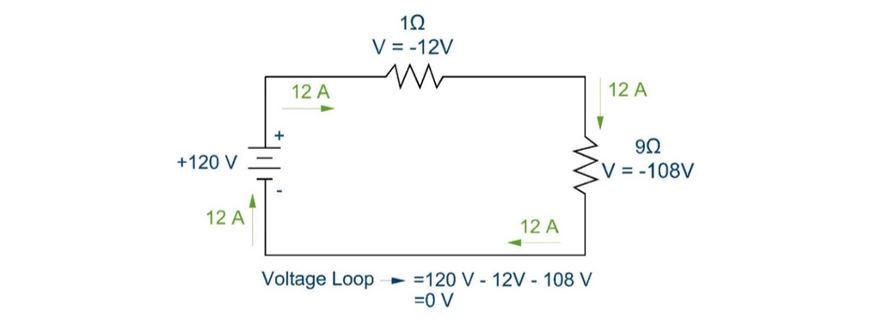
Figure 2: The sum of the voltages around a loop must equal zero.
KVL is also applicable when there is more than one voltage source in a circuit, as seen in the next figure. Notice that the positive and negative terminals of the voltage sources are oriented in the same way, such that both voltage sources contribute positive voltage to the circuit.
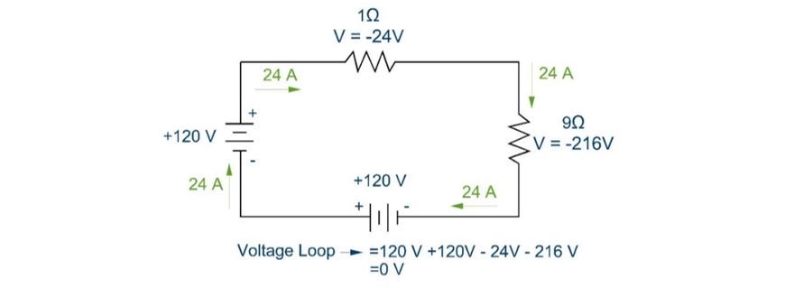
Figure 3: The sum of the voltage around a loop with multiple voltage sources will equal zero.
If the terminals of the two voltage sources were instead situated opposite from one another, then one voltage source would contribute positive voltage and the other would contribute negative voltage. The voltage source that contributed negative voltage would be similar to charging a battery and the positive voltage contribution would be a discharging battery. KVL also applies to circuits with multiple loops. Each loop must have its voltage sum equal to zero.
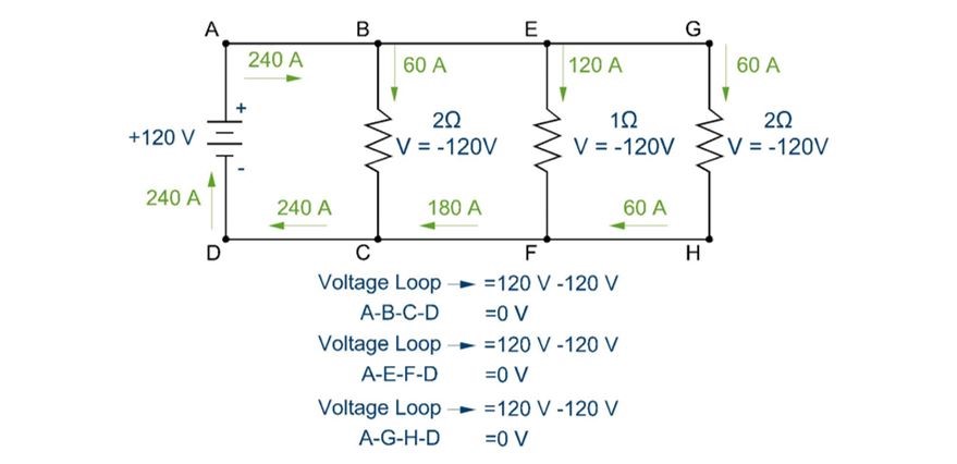
Figure 4: KVL is applicable in any loop.
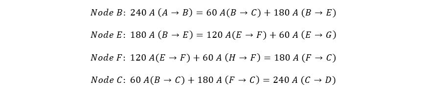
KCL describes the principle that the current entering any node in a circuit must equal the current leaving the node. If you look at the previous circuit, specifically node “B”, you will notice that there is 240 A entering the node and 240 A leaving the node, with 60 A leaving on path B-C and 180 A leaving on path B-E. The next equations show more examples of KCL for various nodes in the previous figure.
Circuit Arrangements
A complex circuit is made up of multiple devices and wires arranged in either series or parallel. These arrangements define the flow of current and the change in voltage with the following principles.
In a series circuit, the resistances are added to determine the equivalent resistance. Once you have a single equivalent resistance value, then you can determine the current flow through the circuit. The main concepts to understand are as follows: (1) Current is constant through a series circuit and (2) resistances are summed to determine equivalent resistance.
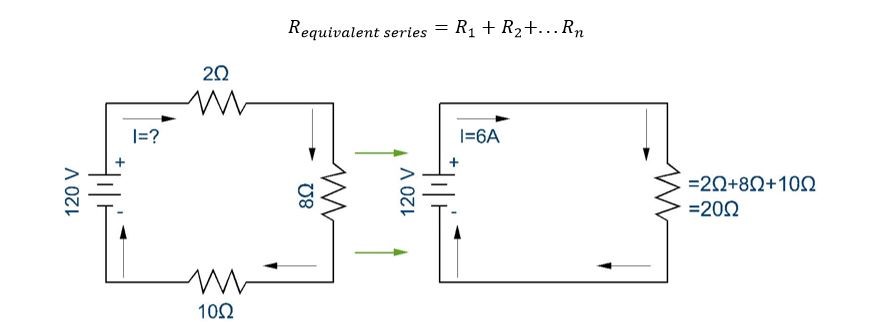
Figure 5: The equivalent resistance for resistors in series is found by adding the resistances.
Once the equivalent resistance is found, the current can be calculated: I=V/R_equiv=6A. Then, the voltage drop and power across each resistor can be found.
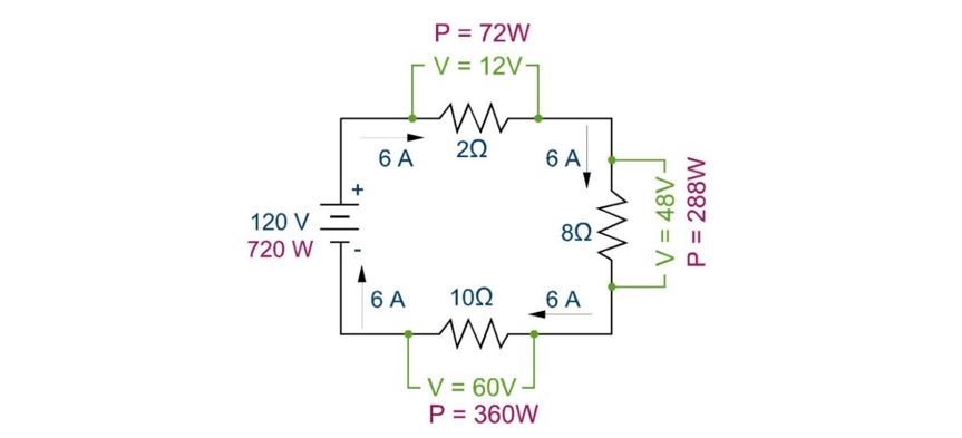
Figure 6: Voltage drop and power use in a series circuit.
Voltage Drop (Series): In the figure above, the voltage drop is found through each resistor by taking the current flow and multiplying it by the resistance, V=IR. As you can see, the voltage drops add up to 120V in accordance with KVL and the voltage drop magnitude varies directly with the resistance level in accordance with Ohm’s law.
In a parallel circuit, the voltage drop across each path is the same and the circuit splits between the different paths.
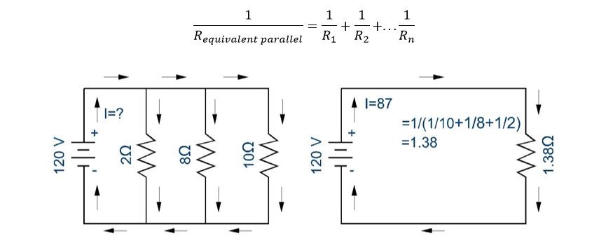
Figure 7: Equivalent resistance of resistances arranged in parallel.
The equivalent resistance will allow you to calculate the main circuit current as 87 amps. To calculate the current through each branch, notice that the voltages across each parallel resistor are the same.
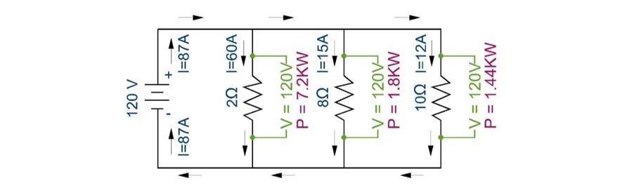
Figure 8: Parallel circuits.
Voltage Drop: In the figure above, the voltage drop is found through each resistor by using KVL and realizing that in every loop the total voltage drop must equal to zero. Thus the voltage drop through resistors, (2 Ω), (8 Ω) and (10 Ω) are all equal to 120 V. The voltage drop through each resistor and the resistance value will allow you to determine the amount of current through each resistor.
. . .
Multiple Sources (Superposition Theorem)
A circuit with a single voltage or current source, such as those in the previous figures are easier to solve. However, when there are two voltage sources, each source will contribute current through a load.
In the simplest scenario of multiple sources, the following rules apply. If the voltage sources are in series, then they can easily be added to form an equivalent voltage source. If the current sources are in parallel, then can be added.
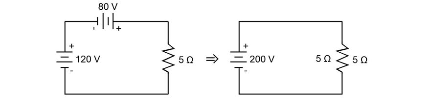
Figure 9: Voltage sources in series without anything between them can be added.
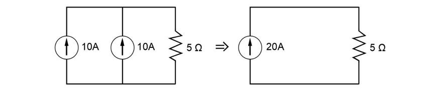
Figure 10: Current sources in parallel can be added to create an equivalent source.
When the circuit becomes more complex and there are multiple sources scattered throughout the circuit, the Superposition Theorem can be used. It basically says that for any linear circuit (i.e. circuits with only resistors, capacitors, and inductors) the current contributed from each separate source can be added together. To do this you must evaluate each source on its own, while turning off all other sources. When turning off sources, voltage sources become short circuits and current sources become open circuits.
This section is continued in more detail in the technical study guide . Also included are many more practice exam problems.
3.0 THEVENIN & NORTON THEOREMS
The Thevenin & Norton theorems can be used to simplify a complex circuit to a single source and resistance. This method creates a simplified equivalent circuit to help analyze the load in question. Everything around the load becomes the Thevinin or Norton equivalent and acts like a black box. Doing this will help you to easily find the voltage and current across the load, instead of having to go through a complicated KVL/KCL analysis.
On the FE exam, the question may ask you to specifically calculate the Thevenin voltage or the Norton current. Sometimes, the question may just ask you to simplify a complex circuit and you will need to choose whether or not to use the Thevenin or Norton theorems.
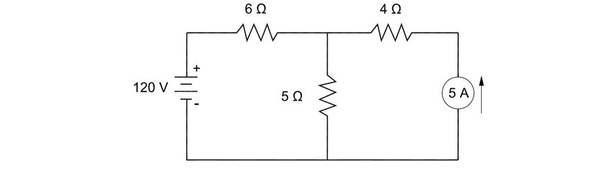
Thevinin EquivalentThe Thevenin theorem involves finding the equivalent voltage and resistance between two points on a circuit. The difficult part is choosing the appropriate points. Typically, you choose points A & B around the load resistor, basically the resistor that you want to know the current and voltage through. In the example below, you should choose points A & B, because we want to know the current and voltage through the 5 ohm resistor.
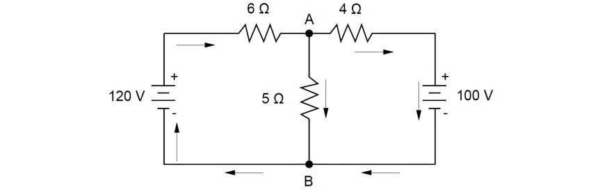
Figure 11: In this example, you will find the Thevenin equivalent circuit between points A & B.
First solve for equivalent resistance. The equivalent resistance is found by removing the voltage sources and the middle resistance value. Find the equivalent resistance of the remaining two resistors in parallel.
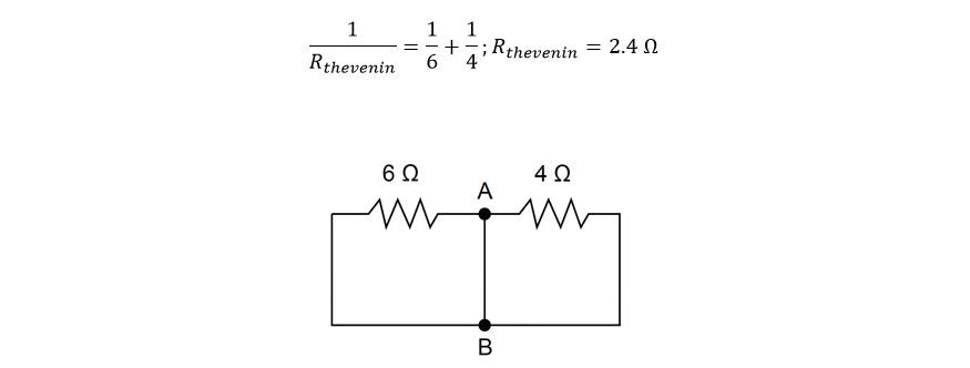
Figure 12: Short the voltages and remove the resistances between the two points A & B. Next, find the equivalent resistance from points to A & B. You should notice that the 6 ohm and 4 ohm resistors are in parallel.
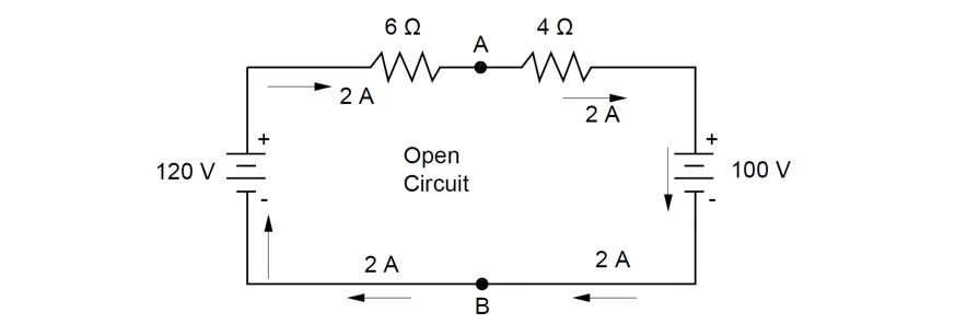
The next step is to find the Thevenin equivalent voltage. For this step, remove the load resistor and open that circuit. Then, find the current through the modified circuit: the effective voltage through this circuit is 20 V and given the total resistance of 10 ohms, the current is 2 A.

Figure 13: The 120 V and 100 V sources are opposed to each other. Current flows from positive to negative terminal, so for the 120 V source current will flow clockwise. The current from the 100 V source wants to flow counter-clockwise, but since it is less than 120 V, then it will be overpowered and current will flow clockwise. However, since these sources are opposing, the effective voltage will only be 20 V, in the clockwise direction.
Now, that you have the current, you can find the voltage drop from A to B.
This voltage drop is the Thevenin equivalent voltage. With the voltage and the equivalent resistance, you can create the Thevenin equivalent circuit.
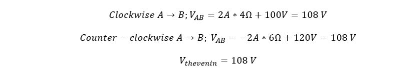
Figure 14: The Thevenin equivalent voltage is 108 V and the equivalent resistance is 2.4 ohms.
Norton EquivalentThe Norton theorem is similar to the Thevenin theorem, except you are finding the equivalent current and resistance between two points on a circuit, instead of the voltage and resistance. The difficult part is again choosing the appropriate points. In the example below, you should choose points A & B. Typically, you choose points A & B around the load resistor, basically the resistor that you want to know the current and voltage through. In the Thevenin equivalent circuit, you will get resistors in series. In the Norton Equivalent circuit, the end result is resistors in parallel.
This section is continued in more detail in the technical study guide . Also included are many more practice exam problems.
4.0 NODE AND LOOP ANALYSIS
Node and loop analysis use the KVL and KCL techniques. The node analysis uses the KCL technique and the loop or mesh analysis uses the KVL technique. This is just another technique that you can use to solve any circuit problem you encounter on the Electrical FE exam. You should only use this technique if you can’t solve the problem with the parallel/series circuit techniques of KCL/KVL. This technique is also separate from the Thevenin & Norton theorems. Those theorems should only be used if specifically called for in the problem.
Node AnalysisThe nodal voltage analysis is basically the KCL technique but you substitute voltages divided by resistances for the currents into and out of a node. You also assign voltages at various points to determine the current. For every resistor, you assign a nodal voltage variable at both sides. The difference between the voltages at those points defines the voltage across that resistor. When you divide that voltage difference by the resistance, you will get the current. The following will take you through a couple of examples of using Node Analysis. This is a good skill to have for analyzing circuits.
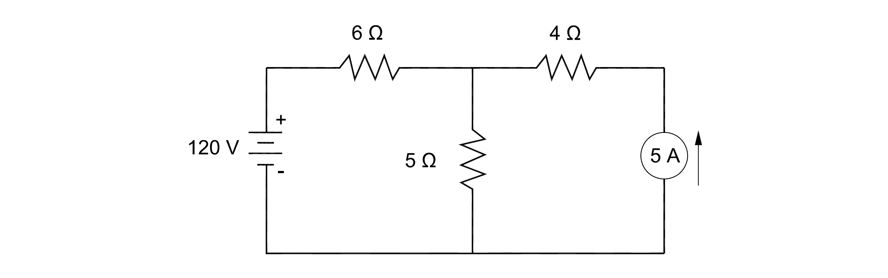
Node Analysis Example 1: Solve for the voltages and currents in the diagram below.
Step 1: Assign each node as a voltage variable. The first step in conducting node analysis is to assign nodes at either side of each component (resistor, inductor and capacitor). You also need to assign a 0 V location. Typically you should select the negative side of the battery.
Step 2: Assign currents, currents flow from positive to negative terminal of batteries. Now, write KCL equations for all of the complex nodes. The complex nodes are those that have more than 2 connections, so nodes B and D. But in order to write KCL equations, you need to assign currents through each component as shown in the diagram below.
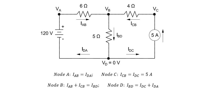
Side note: From the Superposition Theorem, we know that the current source will be an open circuit when analyzing the voltage source, which means the only contribution to the 4 ohm resistor is the 5A current source, ICB=IDC=5A.
. . .
Loop/Mesh Analysis
The loop current analysis is basically the KVL technique but you substitute currents multiplied by resistances for the voltages around a loop. You also loop currents at various paths in the circuit. For every resistor, you assign a voltage drop and every voltage source you add voltages. When you multiply the loop current by the resistance, you will get the voltage drop. The following will take you through a couple of examples of using Loop Analysis. This is a good skill to have for analyzing circuits.
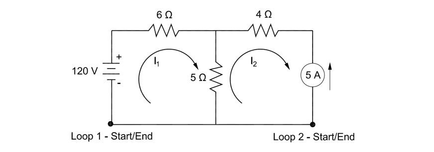
Loop Analysis Example 1: Find the currents and voltages in the circuit below.
Step 1: Assign loop currents in the individual loops. The first step in conducting loop analysis is to assign loops. You also need to assign start and end locations for each loop. For each loop, the start and end locations are the same.
Step 1: Assign loop currents in the individual loops. The first step in conducting loop analysis is to assign loops. You also need to assign start and end locations for each loop. For each loop, the start and end locations are the same.
Step 2: Write KVL equations for each loop. The next step is to write the KVL equations for each loop. Remember that the sum of the voltages along a loop will equal zero
This section is continued in more detail in the technical study guide . Also included are many more practice exam problems.
5.0 WAVEFORM ANALYSIS
Alternating current is most commonly used in power applications. Alternating current describes the alternating directions of flow in a circuit. Current quickly alternates flow direction from positive to negative many times a second. In the figure below, positive current is shown flowing in a clockwise direction in the figure on the right and this flow direction corresponds to the positive portions of the graph on the left.
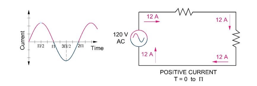
Figure 15: Alternating current consists of positive and negative flowing current. This figure shows positive current flow.
In the next figure, negative current is shown flowing in a counter-clockwise direction. The current flow in the figure on the right corresponds to the negative portions of the graph on the left.
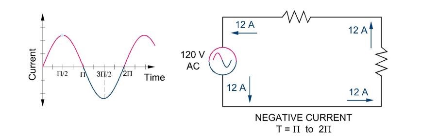
Figure 16: Alternating current consists of positive and negative flowing current. This figure shows negative current flow.
FrequencyThe frequency of an alternating current wave is the number of cycles completed in one second and is given in units of hertz. For example, in the USA, the standard frequency for alternating current is 60 hertz (HZ). This means that 60 cycles are completed in one second. In Europe, the standard is 50 hertz (HZ). In the previous figures, 1/60 seconds would correspond to the 2π value for one cycle is completed at 60 Hz. 1/50 seconds would complete one cycle for 50 Hz.

Another term that is closely related to frequency is angular frequency. Angular frequency is the rotational frequency of alternating current and is given in terms of radians per second. Essentially you are converting a cycle into angular units. For example, if one rotation is completed in one second, then the angular frequency is 2π radians per second. If 60 rotations were completed in one second, then the angular frequency is 120π rad/s. Remember that a generator rotates to produce the frequency in current. That is why the current can be represented as a waveform and angular frequency is useful in analyzing these waveforms. Angular frequency is related to physical frequency through the following equation.

RMS and Max
In an AC circuit, the voltage and current are constantly varying in magnitude over time, see the y-axis in the figure below. The RMS method is used to find the average or effective value of this constantly varying value. You may want to simply calculate the average over time, but in a simple AC circuit, the average of the voltage and current will be zero because there are positive and negative values that will cancel each other out. Instead, the root mean square (RMS) is used. The root mean square is found by taking the sum of the voltage or current at “n” number of points along the waveform, squaring each value, summing all “n” values, taking the square root of the sum, then dividing by the number of “n” points. By squaring the values, the negative values are accounted for.
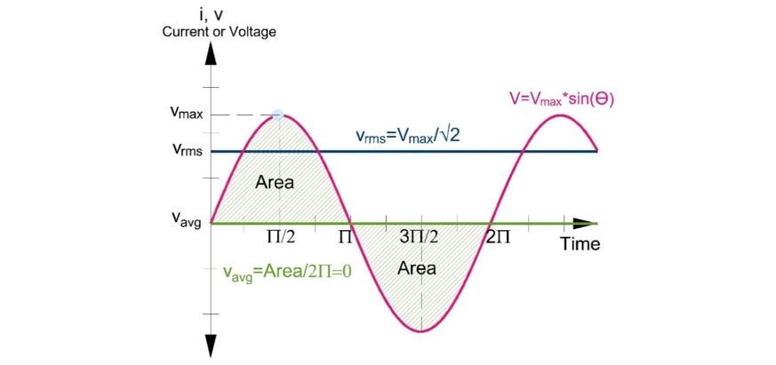
Figure 17: This figure shows the relationship between average, root mean square and maximum values in a sine wave.
The fundamental equation for calculating RMS is shown below. The variable “V” is used for voltage but this variable can also be exchanged for “I” for a current waveform.

The RMS equation can be written for a continuous function, f(t), by taking an integral, in lieu of summing, across an infinite number of “n” points along the time period T. The equation is summarized below.
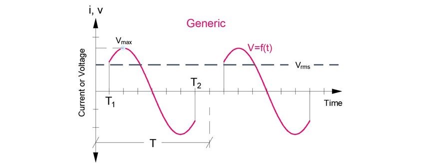
Figure 18: For a function, f(t), the RMS is the square root of the integral of the square of the function across time period T.

The following is a summary of the RMS equations for the most common waveforms. The equations were all derived from the generic equation above.
Perhaps the most important RMS equation you should know is the RMS equation for a sinusoidal waveform. This is most commonly used for the analysis of AC circuits. In a basic sinusoidal waveform, as shown in the figure below, the RMS value is 0.707 times the peak value of the sinusoidal graph.
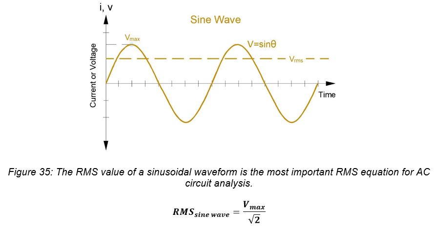
Figure 19: The RMS value of a sinusoidal waveform is the most important RMS equation for AC circuit analysis.

This section is continued in more detail in the technical study guide . Also included are many more practice exam problems.
6.0 PHASORS
This section is continued in more detail in the technical study guide . Also included are many more practice exam problems.
7.0 IMPEDANCE
This section is continued in more detail in the technical study guide . Also included are many more practice exam problems.
8.0 PRACTICE PROBLEMS
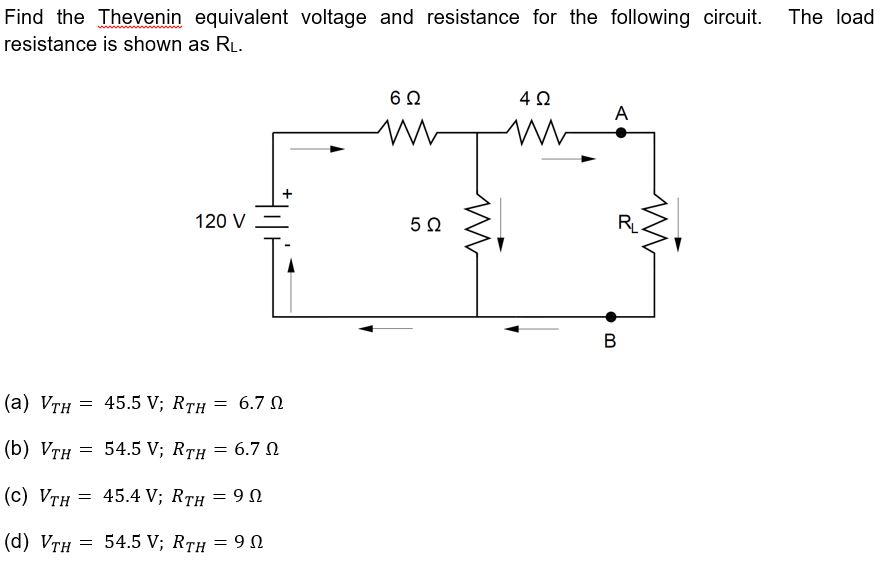
8.1 PRACTICE PROBLEM 1 – THEVENIN
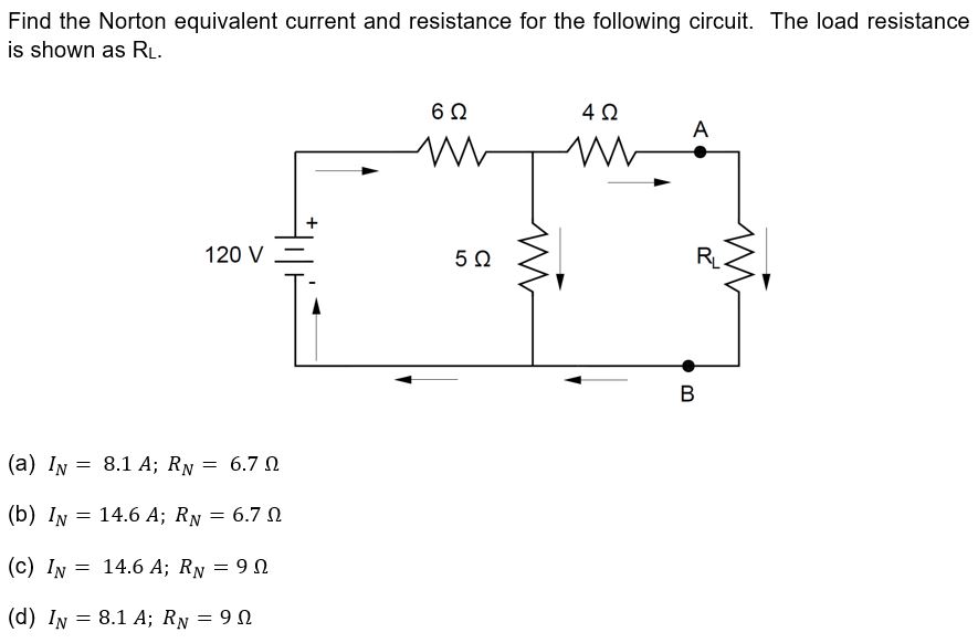
8.2 PRACTICE PROBLEM 2 – NORTON
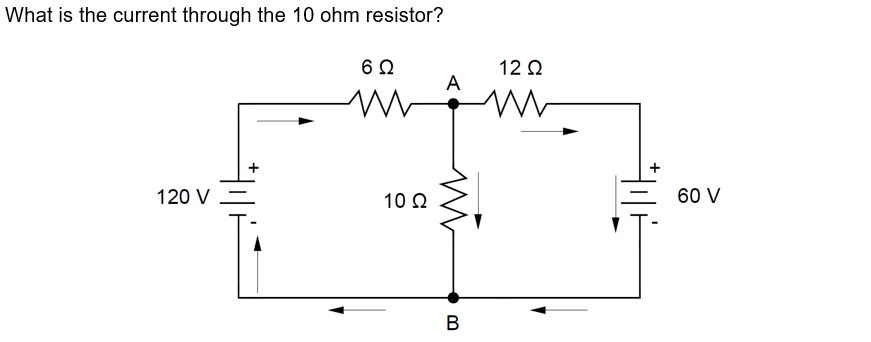
8.3 PRACTICE PROBLEM 3 - KVL
Practice Problems 4 through 15 and all solutions included in the technical study guide, along with many more practice exam problems.