- HOME
- FE EXAM
- PE EXAM
- DESIGN TOOLS
- COURSES
- STORE
- ABOUT
- CONSULTING
![]()
Engineering Pro Guides is your guide to passing the Mechanical & Electrical PE and FE Exams
Engineering Pro Guides provides mechanical and electrical PE and FE exam technical study guides, practice exams and much more. Contact Justin for more information.
Email: contact@engproguides.com
FE EXAM TOOLS
Heat Transfer for the
Mechanical FE Exam
by Justin Kauwale, P.E.
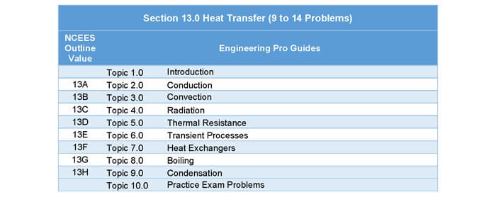
1.0 Introduction
Heat Transfer accounts for approximately 9 to 14 questions on the Mechanical FE exam. The heat transfer principles tested on the FE Mechanical exam are shown in the outline below. There are three main areas of heat transfer: conduction, convection and radiation. Conduction is the transfer of heat through contact. In this type of heat transfer, common skills needed include finding overall heat transfer coefficients, finding insulation values and temperature transitions through materials. Convection is the transfer of heat through a moving fluid. This is most commonly seen in heat exchangers as moving hot fluids transfer heat to cool fluids. The main skill needed in this area include finding the convective heat transfer coefficient through the Nusselt number, Reynolds number and/or Rayleigh number. The final type is radiation, which will require finding the radiative heat transfer coefficient and finding the radiative heat transfer between an object and its surroundings.
The last three topics are heat exchangers, boiling and condensation. For heat exchangers, you must be able to calculate the log mean temperature difference for various types of heat exchangers and the heat transfer between the hot and cold fluid.
2.0 Conduction
The three modes of heat transfer are (1) Conduction, (2) Convection and (3) Radiation. Following this discussion, this section will delve into the primary application of heat transfer concepts in the HVAC and Refrigeration field, which is Cooling and Heating Load Calculations. Another important application of heat transfer is heat exchangers, which will be discussed in this section and in the Mechanical Systems section. Finally, determining insulation requirements is discussed. Determining insulation requirements is an important and practical skill and can be used for determining the needed insulation for pipes, ducts, walls and roofs.
Conduction is a method of heat transfer through a medium or multiple mediums in physical contact due to a temperature difference. In the HVAC and Refrigeration field, heat transfer due to conduction is most commonly calculated during cooling load calculations for wall and roof heat loads.

3.0 Convection
Convection is the second mode of heat transfer and is defined as the transfer of heat through the movement of fluids. In the HVAC and Refrigeration field, convective heat transfer can be found in heating and air conditioning systems, whenever a moving fluid passes over a surface at a different temperature.
One of the most common examples of convection is natural convection in a non-mechanically ventilation/air conditioned building. As people enter a building, the lights get turned on and the sun heats the building, the air in the building begins to get warmer. The warm air is less dense than the air around it and begins to rise up and out of the building. The empty space left by the warm air is then replaced by cooler outside air and the cycle continues. This convective heat transfer through the movement of air is called natural convection. It is referred to as natural because it does not rely on a mechanical source like a fan to move the air.

Convective heat transfer has a similar equation to conductive heat transfer, except the U-Factor or R-Value is replaced with the convective heat transfer coefficient. This convective heat transfer coefficient characterizes the moving fluid by taking into account its viscosity, thermal conductance, temperature, velocity and it also characterizes the surface that the fluid is moving upon.

4.0 Radiation
The third and final mode of heat transfer is radiation. This heat transfer mode is very complicated and differs between theory and application in the HVAC and Refrigeration field. In theory, radiation heat gains for a typical building’s window must be calculated with a computer program like Trane Trace 700, Carrier HAP or any other load calculation program. Radiation heat gains are simplified in hand calculated application and it is the opinion of the writer that the simplified equations for radiation are what can be tested on during the PE exam. Thus only the simplified equations will be discussed in this section and the subsequent sections.
Radiation is the mode of heat transfer that requires no matter to transmit heat. All objects above absolute zero are said to radiate or project heat from its surface. For HVAC and Refrigeration the primary heat gain due to radiation is from solar radiation. Heat is radiated from the sun and transmitted to a building either by heating up the outer surface or transmitting through windows and skylights. These specific examples of solar radiation are described further in the Cooling Load Calculations part of this section.

5.0 Thermal Resistance
Thermal Conductivity
The thermal conductivity for various materials can be found in ASHRAE Handbook – Fundamentals. Thermal conductivity is a measure of how well a material conducts and promotes heat transfer. For example, metals are excellent conductors and thus have a high conductivity. Aluminum has a thermal conductivity of 128 Btu/(hr*ft*℉) and iron has a conductivity of ~30 Btu/(hr*ft*℉). Poor conductors include materials like wood (Douglas fir –0.0833 Btu/(hr*ft*℉)) and insulation materials (Cellular Glass - 0.0275 Btu/(hr*ft*℉) ; Glass Fiber – 0.0221Btu/(hr*ft*℉)).
It is important to note that often times, thermal conductivity is given in units of(Btu*in)/(hr*〖ft〗^2*℉),. This value is basically a thermal conductivity value per inch thickness of materials. Insulation, masonry, plastering and wood materials often have thermal conductivity per inch of materials. For example, cellular glass has a unit thermal conductivity of 0.33(Btu*in)/(hr*〖ft〗^2*℉)), which means that for an inch in thickness of cellular glass material the thermal conductivity is 0.33.
Besides thermal conductivity, materials can also be classified by their R-Value of their U-Factors as shown below.
U-Factor/R Value
U-Factor stands for the overall heat transfer coefficient and it is representative of a material’s ability to conduct heat. Similarly to thermal conductance, a higher U-factor value has a higher ability to conduct and transfer heat. U-factor is related to thermal conductance by the following formula.

This equation assumes that U does not vary based on temperature. For purposes of the exam, this is a safe assumption.
R-Value stands for thermal resistance and it is representative of a material’s ability to resist heat. This is opposite of the U-Factor and thermal conductance which are measures of a materials ability to conduct heat. The relationship between the R-Value, U-Factor and thermal conductance is shown in the following formula.

This equation assumes that R does not vary based on temperature. For purposes of the exam, this is a safe assumption.
R-values are typically used in the HVAC and Refrigeration field to describe building insulation and materials. For example, insulation manufacturers provide product data for their various products and the key value shown on the product data is the R-Value based on different thicknesses.

Notice that the unit R-Value is 5 for 1” of insulation. The corresponding R-values for various inches of thicknesses are found by simply multiplying the thickness in inches by the R-value for 1” of insulation, refer to the below equation.

A must have skill for the aspiring professional engineer is to be able to calculate the overall heat transfer coefficient, U-factor for a wall, roof, duct or pipe. The method in which the overall heat transfer coefficient will be described through this wall example.

It is important to be able to follow the flow of heat from the beginning to the end of this diagram. (1) The first method of heat transfer is convection, warm outdoor air moves across the outer surface of the concrete wall causing the outer surface of the wall to heat up. There would also be radiation loads acting upon the surface of the wall, but for simplicity it is assumed that there are no radiation loads. (2) Next the heat travels from the outer surface of the concrete wall to the inside surface, (3) then to the outer surface of the insulation and through the insulation,(4) then to the outer surface of the gypsum board and through the board. (5) Finally the outer surface of the gypsum board transmits heat both convectively and through radiation to the indoor air.
In order to find the overall heat transfer coefficient, all of the resistances must be summed. It is the opinion of the author, that each method of heat transfer should be converted to its equivalent R-Value in order to keep it simple.


6.0 Transient Processes
Most questions on heat transfer will assume a steady state, but if you encounter a question that has a time component, then you need to use the transient equations. In the NCEES FE Reference Handbook, the only equations on transient heat transfer processes are for conduction. Thus, this section will only focus on those equations, skills and concepts revolving around calculating
6.1 BIOT NUMBER
The Biot number is used as a representation of the heat transfer resistances inside of a substance as compared to the surface of the substance. It tells you whether or not you can use the transient conduction lumped capacitance equations shown in the NCEES FE Reference Handbook. A very small Biot number around 0.1 indicates that the thermal resistance between the surface of the substance and the environment is greater than the thermal resistance inside of the substance.
...
This problem is covered in the practice exam, see the link below.
6.2 CONVECTIVE HEAT TRANSFER BETWEEN SURFACE AND ENVIRONMENT
...
This problem is covered in the practice exam, see the link below.
7.0 Heat Exchanger
Heat exchangers are mechanical devices designed to exchange or transfer heat from a hot fluid to a cold fluid. Heat exchangers are used heavily throughout the HVAC and Refrigeration field, for example a condenser or evaporator in a chiller is simply a heat exchanger. A cooling or heating coil is a heat exchanger that transfers heat from one fluid to another fluid. A chilled water air handling unit transfers heat from the hot air to the chilled water.
There are many different types of heat exchangers that will be briefly discussed, but first it is important to understand the two classifications of heat exchangers, counter-flow and parallel flow heat exchangers. These two classifications describe the relation of the direction of flow between the cold and hot fluid. First the parallel flow heat exchanger, this heat exchanger has both the cold and hot fluids entering at the same end of the heat exchanger. At the beginning of the heat exchanger there is a large difference between the cold and hot fluids and at the end of the heat exchange the difference between cold and hot is reduced, refer to the figure below.

The counter-flow heat exchanger is opposite of the parallel flow heat exchanger. The cold and hot fluids enter at opposite ends. The figure below shows the counter-flow heat exchanger, notice the change in directional arrows.

LOG MEAN TEMPERATURE DIFFERENCE (LMTD)
In heat exchangers that do not have a phase change, heat is transferred from the hot fluid to the cold fluid through the temperature difference between the cold and hot. However, in a heat exchanger as shown in the previous figures, the temperature difference between the cold and hot fluids is not always constant and depends on the location in the heat exchanger. Thus the log mean temperature difference is used. The LMTD describes the logarithmic average temperature difference between the cold and hot fluid through a generic heat exchanger (counter or parallel). LMTD cannot be used for heat exchangers with a phase change like a boiler or condenser. The equation for LMTD is shown below.

The LMTD is then used to calculate the total heat exchanged by the heat exchanger through the following equation. The U-value is the heat transfer coefficient of the heat exchanger which is given by the heat exchanger manufacturer. The Area value is the total area where heat exchange occurs, which is given by the heat exchanger manufacturer.

HEAT BALANCE
Often times in the HVAC and Refrigeration field, a heat balance is conducted on a heat exchanger to show that a balance of heat loss from the hot fluid is shown as a heat gain to the cold fluid. For example, cooling coils are heat exchangers that transfer heat from air to water. The heat balance governing this heat transfer would be as shown below.

If there is a phase change, then the following equation can be used. Heat balances are discussed further in the Refrigeration Section, Mechanical Systems and the Psychrometrics section. Basically, heat balances are integral to the HVAC and Refrigeration field, but luckily the equations governing a heat balance are fairly simple.

8.0 Boiling
This problem is covered in the practice exam, see the link below.
9.0 Condensation
This problem is covered in the practice exam, see the link below.
10.0 Practice Problems
10.1 PROBLEM 1: CALCULATE OVERALL HEAT TRANSFER COEFFICIENT
This problem is covered in the practice exam, see the link below.
10.2 PROBLEM 2: CALCULATE OVERALL HEAT TRANSFER COEFFICIENT
This problem is covered in the practice exam, see the link below.
10.3 PROBLEM 3: CALCULATE THE REYNOLDS NUMBER
250 GPM of 120F water flows through a 4” diameter pipe that is located in the ceiling of a building. Assume the water in the pipe is not under extreme pressure. Calculate the Reynolds number of the fluid inside the pipe.
a) 57,734
b) 295,941
c) 355,745
d) 136,836,344
10.4 PROBLEM 4: CALCULATE THE CONVECTIVE HEAT TRANSFER COEFFICIENT
250 GPM of 120F water flows through a 4” diameter pipe that is located in the ceiling of a building. Calculate the convective heat transfer at the fluid inside the pipe. Assume the water in the pipe is not under extreme pressure.
a) 556 Btu/(h*〖ft〗^2*℉)
b) 5,182 Btu/(h*〖ft〗^2*℉)
c) 6,738 Btu/(h*〖ft〗^2*℉)
d) 12,784 Btu/(h*〖ft〗^2*℉)
10.5 PROBLEM 5 – HEAT EXCHANGER
10.6 PROBLEM 6 – HEAT EXCHANGER
10.7 PROBLEM 7 – HEAT EXCHANGER
10.8 PROBLEM 8 - CONDENSATION
A closed feedwater heater is used to heat incoming 23.9 °C water. Saturated steam at 1,723 kPa is used to heat the incoming water. Saturated steam enters the feedwater heater at a mass flow rate of 10% of the incoming water mass flow rate. The condensate leaves as a saturated liquid. What is the outgoing temperature of the water?
c_(p,water)=4.18 kJ/(kg-K)
(A) 61 °C
(B) 70 °C
(C) 78 °C
(D) 83 °C
10.9 PROBLEM 9 – NTU METHOD
This problem is covered in the practice exam, see the link below.
10.10 PROBLEM 10 - TRANSIENT
A motor is modeled as a box with dimensions, 3’ x 5’ x 1’. The motor is turned off and is at a temperature of 300 K. Assume the properties for the motor as shown below. Assume the motor is raised with an open platform. The motor is located in a room that is at a temperature of 300 K. The convective heat transfer coefficient is also shown below. What is the Biot number?
(A) 0.01
(B) 0.10
(C) 0.44
(D) 1.21
10.11 PROBLEM 11 - RADIATION
This problem is covered in the practice exam, see the link below.
10.12 PROBLEM 12 – RADIATION & CONVECTION
This problem is covered in the practice exam, see the link below.